The FASER tracker has been designed to separate and detect two high-energy, oppositely charged tracks originating from a common vertex in the decay volume. For this purpose, three tracking stations are employed, which are separated by two 1 m-long magnets deflecting the charged particle trajectories. The first tracking station is situated right after the decay volume and is followed by additional scintillator station used for triggering. This scintillator station is also used to obtain timing information of the event in FASER so that it can be correlated with pp interactions taking place at the ATLAS IP. The third and final tracking station is followed by another (preshower) scintillator station and the calorimeter.
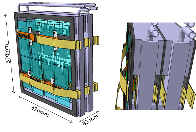
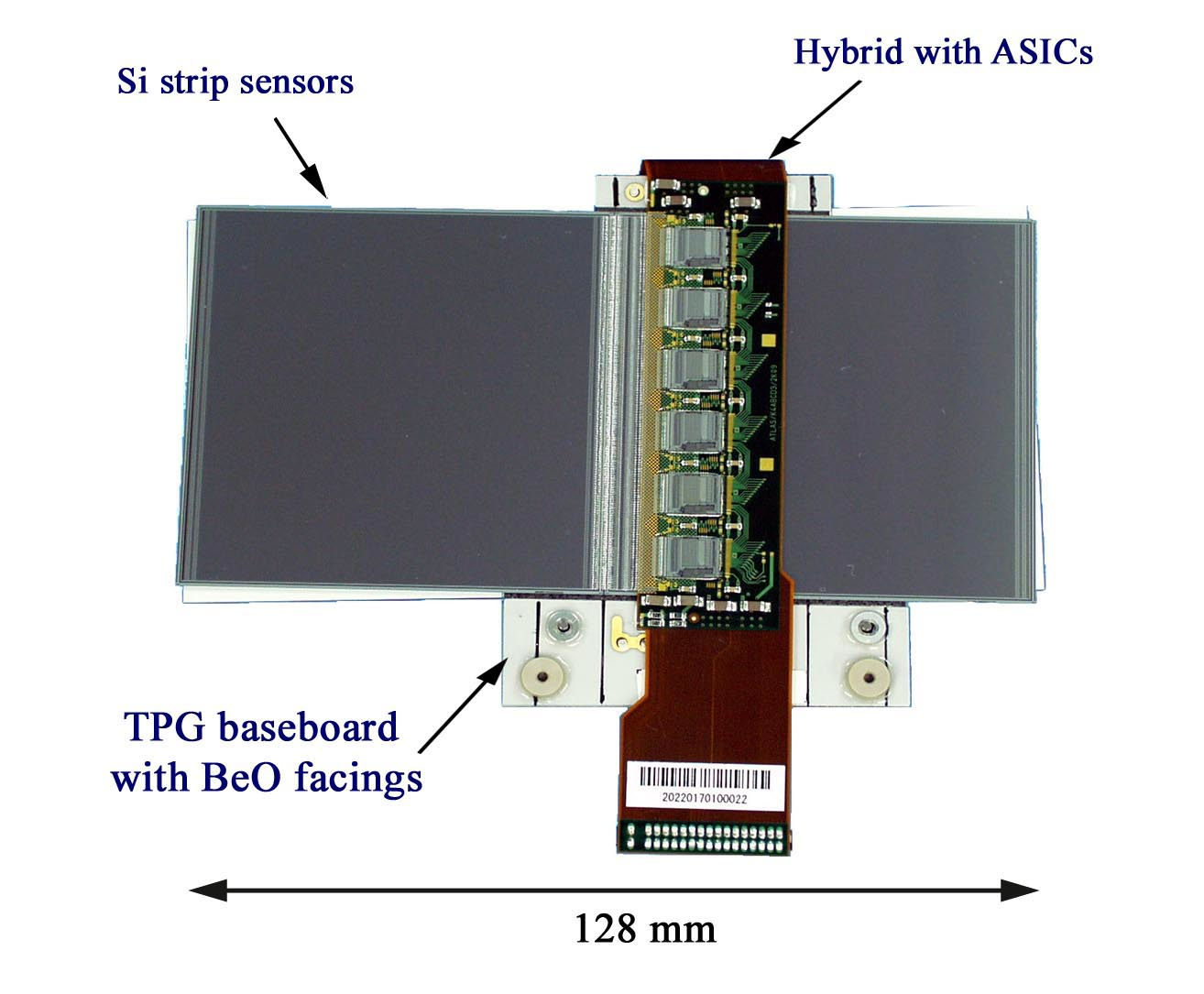
Each tracking station (see Fig. 1) consists of three tracking layers (see Figs 2 and 3) of two pairs of single-sided silicon micro-strip sensors. In total, 72 spare ATLAS semiconductor strip tracker (SCT) modules (see Fig. 4) are used with 8 per tracking layer. These were carefully selected based on a series of quality assurance tests so that the FASER spectrometer is based on technology that has already proven reliable during LHC Run 1 and 2.
Alignment between different tracking layers within a single tracking station is achieved by mounting them to aluminium module frames, which also provide an interface to other services (cables, water pipes, dry air pipes) and tothe FASER support system with an adjustable mechanism for alignment between different tracking stations. In addition, measured muon flux going though FASER is used to improve the alignment further.
An additional cooling system is installed in the TI12 tunnel to remove heat from the onboard ASICs. The optimal working temperature for the tracking stations is kept in the 5-10°C range by the use of chilled water and a dedicated chiller placed in TI12 close to the detector. In order to prevent overheating of SCT modules in case of a cooling failure, the tracker’s detector control system controls and monitors the power supplies, chiller, module temperatures, and environmental sensors inside the stations. Humidity inside the tracker stations is controlled using compressed air with a guaranteed dew point below −40°C.
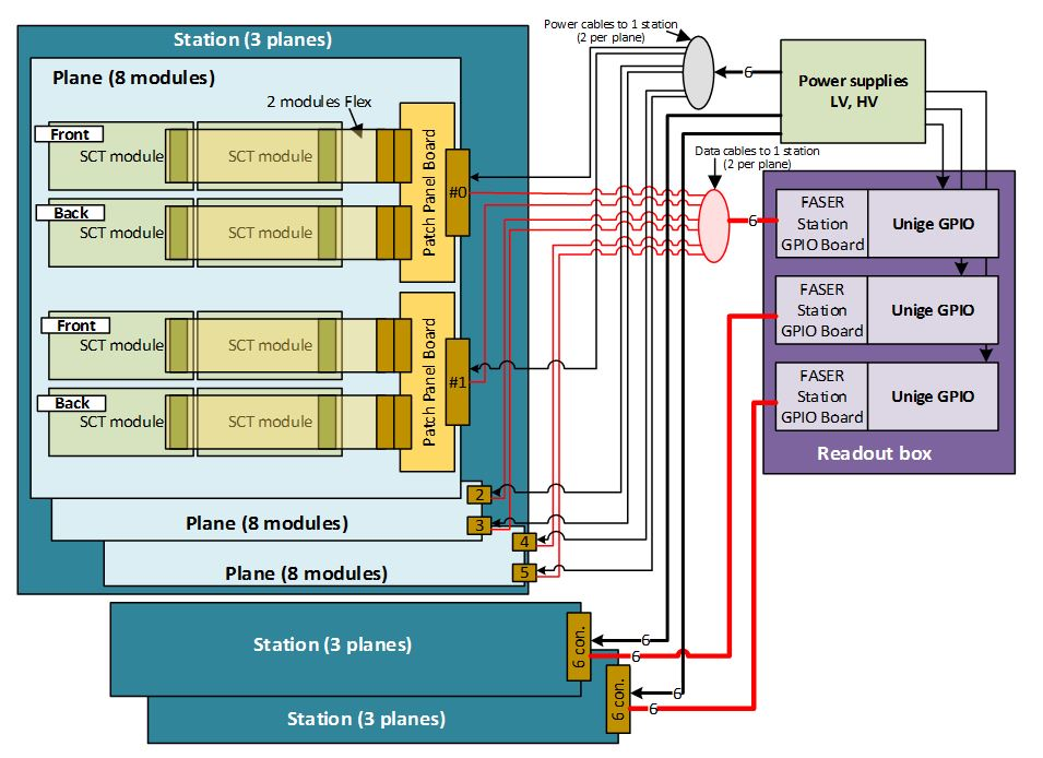
The FASER tracker readout system has been designed based on the general-purpose ‘Unige GPIO board’, which was developed by the University of Geneva for slow control and readout of particle physics ASICs, detectors tests, and qualification. Adapter boards have been designed to allow communication with the SCT modules. Fig. 5 presents an optimized architecture with one ‘Unige USB3 GPIO’ board per station, each driving three planes.
For the best physics performance, required track separation in the spectrometer should be at least 300 µm. The expected efficiency of horizontal track separation in the first tracking station is shown in Fig. 6 as a function of the energy of the decaying dark photon for two representative dark photon masses. We illustrate possible GEANT4-simulated trajectories of electron and positron produced in such a decay event in Fig. 7. The strategy for reconstruction of tracker data is similar to that used in ATLAS. Combinatorial pattern recognition is used to identify track candidates passing through different tracker planes. The final track fit uses all available information, with extrapolation through a realistic model of the detector material (including energy loss and multiple scattering) and a detailed map of the magnetic field.
Importantly, the expected trigger rate ~600 Hz in the FASER spectrometer is much lower than in typical large-scale LHC experiments. Combined with a very small occupancy of the tracking detector (generally a few hits per plane from a single muon traversing the detector in addition to a small number of noise hits) and a low radiation level in the TI12 tunnel, this leads to significant simplification (in comparison with ATLAS, for example) of SCT module readout in FASER.
Fig. 1: FASER tracking station.
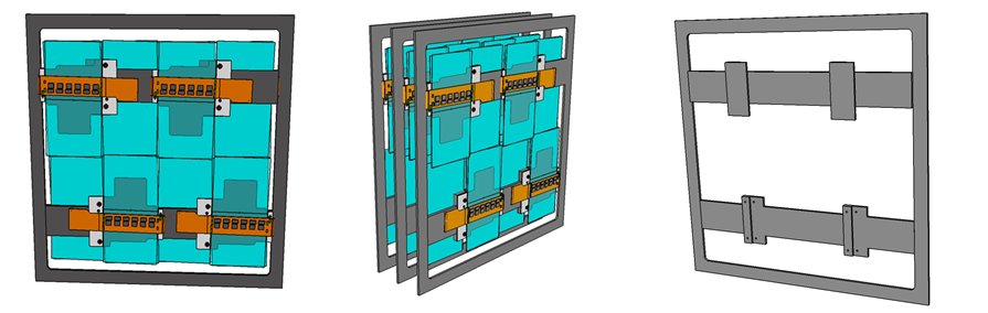
Fig. 2: Left: Module frame with a tracker plane mounted inside. Center: Three module frames assembled into a tracking station. Right: The module frame itself.
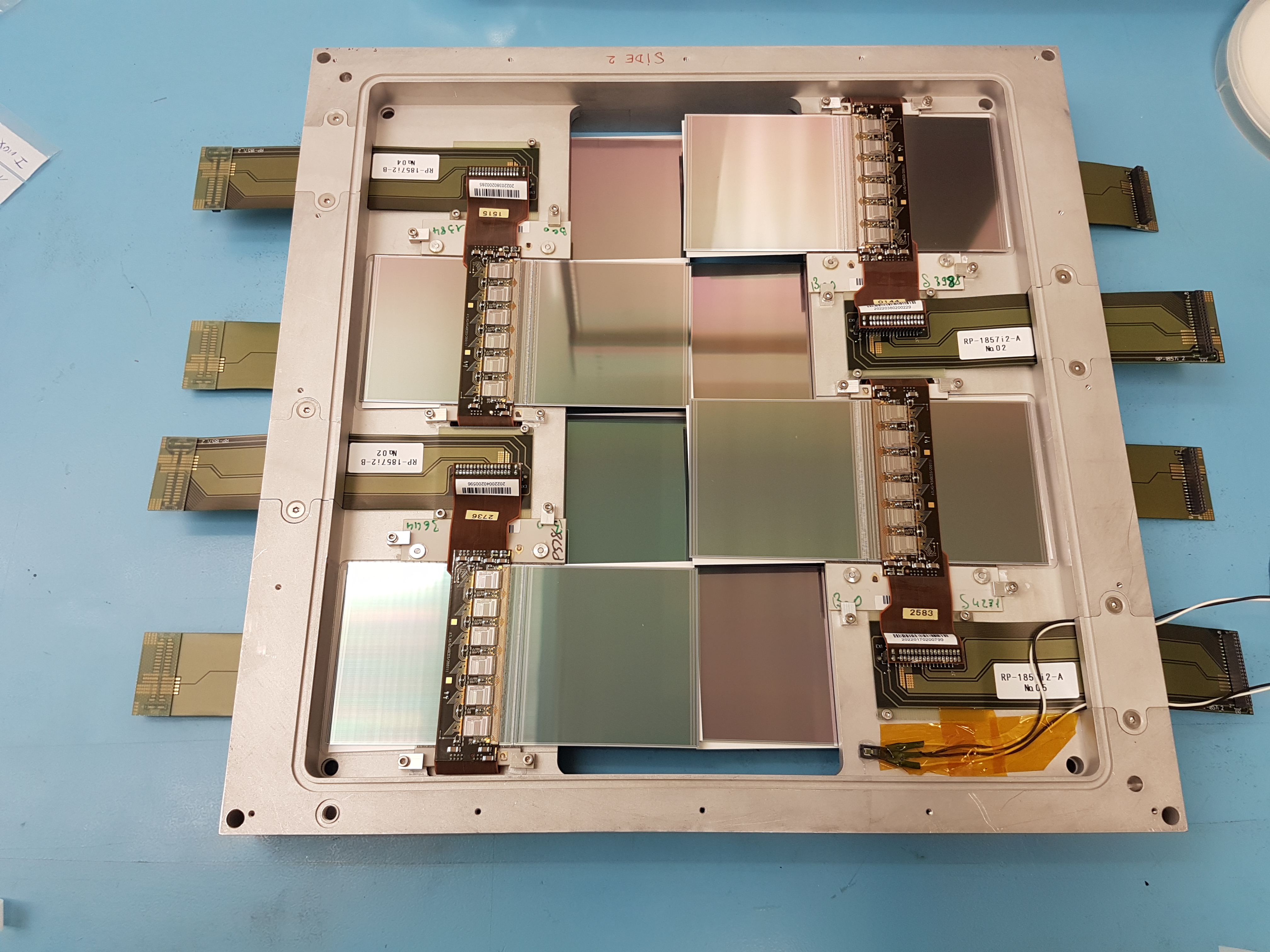
Fig. 3: FASER prototype tracking layer, with 8 SCT modules and flex cables mounted onto a custom made frame (which includes cooling).
Fig. 4: ATLAS SCT barrel module used in FASER.
Fig. 5: The FASER tracker readout architecture.
Fig. 6: Two-track separation efficiency based on isolated space-points in the first tracker plane for the indicated dark photon masses and momenta. Dark photon decays are uniformly distributed over the length of the 1.5 m decay volume.
Fig. 6: GEANT4 simulation of two oppositely charged tracks separating in the magnetic field as they pass through the FASER spectrometer and enter the calorimeter at top right.


